- 您现在的位置:买卖IC网 > Sheet目录341 > MAX8790ETP+T (Maxim Integrated)IC LED DRVR WHITE BCKLGT 20-TQFN
�� �
�
�Six-String� White� LED� Driver� with� Active�
�Current� Balancing� for� LCD� Panel� Applications�
�clamped� to� a� level� set� with� the� OV� feedback� input.�
�When� this� elevated� output� voltage� is� applied� to� the�
�undamaged� strings,� excessive� voltage� drop� develops�
�across� the� FB_� pins.� If� the� resulting� HVC� signal�
�exceeds� V� CC� +� 0.6V� for� greater� than� 65ms,� the� fault�
�latch� is� triggered� to� protect� the� circuit.�
�LED-Short� and� String� Mismatch� Protection�
�Normally,� white� LEDs� have� variations� in� forward-voltage�
�drop� of� 3.1V� to� 3.6V.� The� MAX8790� can� tolerate� slight�
�mismatches� between� LED� strings.� When� the� sum� of� the�
�LED� forward� voltages� creates� a� mismatch� in� the� strings�
�so� the� HVC� signal� exceeds� V� CC� +� 0.6V� for� greater� than�
�65ms,� the� fault� latch� is� triggered� in� much� the� same� way�
�as� the� circuit� responds� to� open� string� faults.� Similar� pro-�
�tection� is� activated� when� an� LED� is� shorted.�
�The� larger� the� number� of� series-connected� LEDs� (N),�
�the� smaller� the� tolerable� mismatch� between� LEDs:�
�∑� Error� <� V� CC� +� 0� .� 6� V� ?� V� SAT�
�N�
�V� SAT� ≈� 450mV� and� V� CC� =� 5V�
�∑� Error� <� 5� .� 150� V�
�N�
�For� N� =� 8,� the� average� error� per� LED� =� 644mV.�
�For� N� =� 10,� the� average� error� per� LED� =� 510mV.�
�The� larger� the� total� mismatch,� the� larger� the� voltage�
�drop� required� across� each� current� source� to� correct� for�
�the� error,� and� therefore� the� larger� the� dissipation� within�
�the� MAX8790.�
�Dimming� Control�
�The� MAX8790� features� both� analog� and� digital� dim-�
�ming� control.� Analog� dimming� can� provide� potentially�
�higher� converter� efficiency� because� of� low� voltage� drop�
�across� each� WLED� when� the� current� is� low.� Digital� dim-�
�ming� (DPWM)� provides� less� WLED� color� distortion�
�since� the� WLED� current� is� held� at� full� scale� when� the�
�WLED� is� on.�
�The� MAX8790’s� dimming� control� circuit� consists� of� a�
�PLL,� a� digital� comparator,� and� a� DAC.� The� controller�
�provides� 100:1� dimming� range� through� either� analog� or�
�digital� control� methods.� Both� methods� translate� the�
�duty� cycle� of� the� BRT� input� into� a� control� signal� for� the�
�LED� current� sources.� In� analog� dimming� mode,� the� cur-�
�rent-source� outputs� are� DC� and� the� BRT� duty� cycle�
�(12.5%� <� D� BRT� <� 100%)� modulates� the� amplitude� of�
�the� currents.� For� D� BRT� <� 12.5%,� the� LED� current� is� digi-�
�D=�
�t� ON�
�t� BRT�
�Average� Error� Per� LED� =�
�5.150V�
�N�
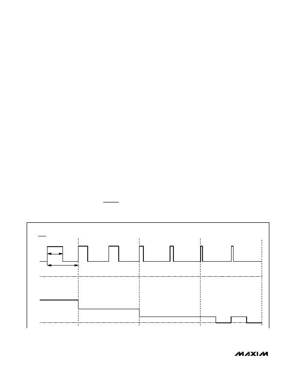
�tally� modulated� to� reduce� the� average� LED� current�
�down� to� 1%� of� full� scale.� The� PLL� detects� the� BRT� fre-�
�quency� and� phase,� and� adjusts� the� current-source�
�amplitude� and� duty� cycle� synchronously� (see� Figure� 4).�
�ANALOG� DIMMING� MODE�
�BRT�
�D� =� 50%�
�t� ON�
�D� =� 30%�
�D� =� 12.5%�
�D� =� 6.25%�
�t� BRT�
�I� LEDMAX�
�I� LED�
�0A�
�Figure� 4.� LED� Current� Control� Using� Analog� Dimming� Mode�
�14�
�______________________________________________________________________________________�
�发布紧急采购,3分钟左右您将得到回复。
相关PDF资料
MAX8791GTA+
IC MOSFET DRIVER 8-TQFN
MAX8811EEE+
IC DRVR DL PHASE HS 16-QSOP
MAX8821ETI+
IC LED DRVR WHITE BCKLGT 28-TQFN
MAX8822ETE+T
IC LED DRVR WHITE BCKLGT 16-TQFN
MAX8830EWE+T
IC LED DRVR WHITE BCKLGT 16-UCSP
MAX8831EWE+T
IC LED DRIVR WHITE BCKLGT 16-WLP
MAX8834ZEWP+T
IC LED DRIVR BCKLGT FLASH 20-WLP
MAX8855EVKIT+
KIT EVAL FOR MAX8855
相关代理商/技术参数
MAX8790EVKIT+
功能描述:LED 照明开发工具
RoHS:否 制造商:Fairchild Semiconductor 产品:Evaluation Kits 用于:FL7732 核心: 电源电压:120V 系列: 封装:
MAX8791AGTA+
制造商:Rochester Electronics LLC 功能描述: 制造商:Maxim Integrated Products 功能描述:
MAX8791AGTA+T
制造商:Rochester Electronics LLC 功能描述: 制造商:Maxim Integrated Products 功能描述:
MAX8791BGTA+
功能描述:功率驱动器IC Single-Phase Synch MOSFET Driver RoHS:否 制造商:Micrel 产品:MOSFET Gate Drivers 类型:Low Cost High or Low Side MOSFET Driver 上升时间: 下降时间: 电源电压-最大:30 V 电源电压-最小:2.75 V 电源电流: 最大功率耗散: 最大工作温度:+ 85 C 安装风格:SMD/SMT 封装 / 箱体:SOIC-8 封装:Tube
MAX8791BGTA+T
功能描述:功率驱动器IC Single-Phase Synch MOSFET Driver RoHS:否 制造商:Micrel 产品:MOSFET Gate Drivers 类型:Low Cost High or Low Side MOSFET Driver 上升时间: 下降时间: 电源电压-最大:30 V 电源电压-最小:2.75 V 电源电流: 最大功率耗散: 最大工作温度:+ 85 C 安装风格:SMD/SMT 封装 / 箱体:SOIC-8 封装:Tube
MAX8791GTA+
功能描述:功率驱动器IC Single-Phase Synch MOSFET Driver RoHS:否 制造商:Micrel 产品:MOSFET Gate Drivers 类型:Low Cost High or Low Side MOSFET Driver 上升时间: 下降时间: 电源电压-最大:30 V 电源电压-最小:2.75 V 电源电流: 最大功率耗散: 最大工作温度:+ 85 C 安装风格:SMD/SMT 封装 / 箱体:SOIC-8 封装:Tube
MAX8791GTA+T
功能描述:功率驱动器IC Single-Phase Synch MOSFET Driver RoHS:否 制造商:Micrel 产品:MOSFET Gate Drivers 类型:Low Cost High or Low Side MOSFET Driver 上升时间: 下降时间: 电源电压-最大:30 V 电源电压-最小:2.75 V 电源电流: 最大功率耗散: 最大工作温度:+ 85 C 安装风格:SMD/SMT 封装 / 箱体:SOIC-8 封装:Tube
MAX8792ETD+
制造商:Maxim Integrated Products 功能描述:SOFT SW PWM CNTRLR 1-OUT PWM CNTRLR 600KHZ 14TDFN EP - Rail/Tube 制造商:Maxim Integrated Products 功能描述:SINGLE QUICK- PWM STEP DOWN CONTROL